Work and life in general has been pretty hectic lately so updates have been pretty slow… But I had a user on the FlyByWire discord suggest I make more posts. So I’m going to make an effort to do that.
I ended up buying a real Airbus component. A cockpit door control panel. (119VU) Not the most exciting panel but one of the cheapest. It is also a great source of reference material! Paint color, a korry switch/indicator, toggle switch, pushbutton, backlighting color, dzus fasteners and of course the panel sizes themselves!
Once I got it I spent a while admiring the wiring and trying to reverse engineer it. I eventually got it all lit up and was happy to find that it all worked!
Aside from that ive been collecting a bunch of pictures and reference documents, even some wood and tools! I’m super excited! It looks like I’ll be starting on the pedestal first. In the next post I’ll go into a bunch more detail about all the small things I’m trying to sort out. Like paint colors and actual panel construction.
Some form of display is often vital on your arduino projects.Let me introduce you to the HD44780 character LCD.
It’s quite a common and cheap display solution that is relatively easy to use. It often finds its way into many arduino starter kits for these reasons. Ive used it a few times in my projects but have always been annoyed by one aspect…. the high amount of pins and the requirement of a resistor for the backlight and a potentiometer for the contrast.
The typical wiring setup for the display
As you can see the board uses up 6 data pins on your board which can be a pain on the smaller boards I’ve been using lately. Then I discovered I2C (I squared C).
I2C is a method of using addresses to run many devices on only 2 data lines.
With this we can run these LCD displays with a total of 4 wires. This is handy on boards like the ESP8266 or ESP32 with few pins. I plan on using a I2C compatible display on a project in the near future. I ordered the larger 4 line version in fact.
The code for the I2C display is quite similar to the regular versions.
#include <Wire.h>
#include <LiquidCrystal_I2C.h>

LiquidCrystal_I2C lcd(0x27,16,2);  // set the LCD address to 0x27 for a 16 columns and 2 row display

void setup() {
  lcd.init();       //initialize lcd screen
  lcd.backlight();  // turn on the backlight
}

void loop() {
  delay(1000);                   //wait for a second
  lcd.setCursor(0,0);            // tell the screen to write on the top row
  lcd.print("LCD TEST");         // tell the screen to write “hello, from” on the top row
  lcd.setCursor(0,1);            // tell the screen to write on the bottom row
  lcd.print("Hello World!");     // tell the screen to write "Hello World!" on the bottom row
}
Sure has been a while since my last update. I’ve been in a bit of a lull in terms of progress on this project, partially due to the current state of the game and also due to my busy schedule as of late. Nevertheless i can show the bit of progress I’ve made since my last post.
As you probably know, the devs decided to use a fan to represent the reactor of the payer’s ship, the fan would spin when the reactor is powered and stop when it is not. I thought this was a neat idea so I decided to follow a similar path on my panel and expand on the concept. I started by sourcing a 5v USB powered PC cooling fan on AliExpress. I bought a 4.5 inch hole saw to make the hole to mount it in. This worked well however i was a bit careless in drilling out the hole resulting in a minor gouge in my panel.
oops >.>
At first I was rather disappointed but then came up with a decent solution. I happened to have a coworker with a 3D printer, he was happy to print me a bezel for the fan which will hide the damage and actually makes it look better in my opinion.
Here you can see the fan, the guard, and the 3D printed ring.
Once assembled into the panel it doesn’t look half bad! I plan to control the speed of the fan to also represent the amount of power the ship has… as you start running low the fan will slow down and eventually stop completely. Also I want to back light the fan with some orange-ish lights to make it look like its glowing from within, perhaps even making the lights flicker as the ship’s power dips.
Here’s the view from the back, you’ll notice I mounted the arduino controller inside and also added a 7-segment display under each meter these displays will just mirror what is represented on the meters. I did this mainly just for the looks but it will probably help with readability in tense combat situations.
You may have also noticed that I added the 8 torpedo tube selection buttons. It took me a while to decide how to arrange them but I eventually decided on 2 offset columns. It looks futuristic without taking up too much space on the panel.
That pretty much showcases all the work that I have done since the last post. As I mentioned earlier my schedule lately has been pretty hectic. I cant say when my next update will come but hopefully it wont take as long as this one did.
I think a vision most builders have for their completed panels are having them all lit up with loads of various LEDs and indicators. I too have the same vision. However one thing to keep in mind is that some LEDs can be quite bright, especially the blue and white LEDs.(I’ll come back to this)
Now if you have even a little electronics knowledge you should know that you cant have an LED hooked directly hooked up to the 5 or 3.3V power supply of your arduino. You NEED a resistor to limit current and prevent killing your precious diodes. For standard 5mm LEDs a resistor somewhere in the range of 220 and 330 ohms is a good place to start. Obviously the more ohms the dimmer the light will become.
The LEDs I bulk ordered from china are quite bright especially when it comes to the Blue and White varieties. Having a bunch lit up shining in your face while your trying to play the game isn’t optimal. So I figured before I bulk order a bunch of resistors I should test each color LED and find a resistor value that gives each color an even and comfortable brightness. At first I thought the best way to do this would be to use a potentiometer in series with the LED to tune the brightness to a level I was happy with then use a multi-meter to measure the resulting resistance value. This is a perfectly acceptable way to do this but then I came across a method I liked a little better. (and is a lot more precise and reliable)
A “programmable” resistor! This board has 63 surface mount resistors on one side and 7 sets of headers on the other. Using the provided pin jumpers you can set the board to have ANY resistance value from 0 to 9,999,999 ohms (almost 10 Megaohms) I picked this up cheap off AliExpress for $2.98 CDN plus $4.90 CDN shipping. It will surely be a handy addition to my toolbox and i’m sure you’ll be seeing me use it down the road.
Ignore the misprints on the board, the max value is NOT 1000 Megaohms as the silkscreen implies. :p
On my day off today I decided to continue work on my panel. I added the 1/4 inch MDF faces and aimed to mount both meters in the tower.
I decided to start with the square meter which will display the ships total power. It was the easier of the to mount in the tower.
To start I simply used the largest hole saw I have and made a hole right in the middle of the square I had to remove.
I then used a jigsaw to carefully remove the rest of the wood. I used spiral cuts to each corner and just kept working at it. This takes a bit of time but usually ends in nice clean cuts. Remember to not make too sharp of turns when using a jigsaw or you risk binding and breaking the blade or even damaging your material.
I was a little on the careful side when making these cuts so I had to do a lot of slow sanding to widen the opening to fit the meter. I used a mix of tapered sanding sponge, Regular sandpaper, and a bar file. Basically just working with what I had on hand.
Eventually it fit and looks fairly good!
The second meter was a bit more complex to mount. First I started by marking the meter’s total footprint and the point to make another hole via a holesaw.
I cut out the hole and then when I went to test fit the meter I realized that the meter wouldn’t sit flush on the panel. This meter had a small protrusion that I didn’t notice so I had to use my dremel to sand and enlarge the hole by quite a bit.
This worked and allowed the meter to sit flat. This picture shows the meters from the back and in it you can really see how differently they mount. Luckily my messy work on the 2nd meter is hidden.
And Just like that both are sitting nicely on the tower! Hope you found the process interesting! I did end up ordering those 8 torpedo tube select buttons I mentioned in my previous post. They will be going on the foot of this tower… in fact this tower will end up being fairly similar to the dev’s MK2 tower.
Again, not too much progress to report. The updates may get a little less frequent than they have been. I had to cut back on some spending due to an unexpected vet bill. >.> However items I have ordered continue to trickle in. One of which is my torpedo launch button!
Momentary Anodized Aluminum Launch Button
I plan on mounting this launch button within a plastic safety cover. We don’t want any accidental fires! I’m hoping the button fits in this cover… might be a bit of a tight fit. We’ll find out when it arrives!
For selecting torpedo tubes I plan on using “elevator-like” illuminated switches. If space permits, I hope to have buttons for all 8 torpedo tubes. Even though the game currently only supports selecting tubes 1-5 via serial. This is being changed in a future update. I have not ordered these buttons yet.
Another item I did receive is a nifty little USB voltmeter/ ammeter. I thought it may prove useful to keep track of my Arduino’s power consumption. I still haven’t decided if a powered USB hub will be enough or if I will need to have an external power supply.
Additionally, I also just got a cheap and super basic mini oscilloscope. Its not particularly needed for anything on this project but I’ve kinda always wanted to mess around with one and couldn’t say no to the price. ($18)
And finally, my tower structure should be ready to receive its 1/4″ MDF front pieces. I just had to add the crosspiece at the end of the foot. It’s top is cut at 15 degrees to be flush with the other pieces. I’ll post my measurements for the towers at a later date.
I’ve always loved the retro feel seven segment displays give off and I feel they are an awesome fit for the aesthetic of “Objects in Space”. Today I was able to overcome a problem that was stumping me for a while… How to display 2 dynamic length integer variables on the same display with blank leading digit padding…. now that’s a mouthful. I’m happy to say I did crack it and manage to come up with something that looks good!
I’m kind of taking a “More is More” approach for building this console. I want new users to be somewhat overwhelmed by all the displays, LEDs, switches, ect. So Id love to have many of these displays on the panel displaying a wealth of info. Not all of which will be immediately useful when playing the game, but in in “reality” would be found in a spaceship bridge. I’m also thinking having an auxiliary panel somewhere displaying the players bank funds on a 7-seg display would be cool…. somehow making it fit “plausible lore” as well.
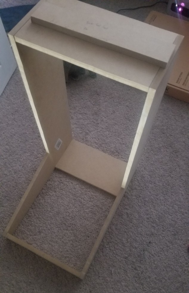
Nothing too exciting today. I cut two support pieces out of half inch MDF and brought my my two side walls together. Now that it can stand on it’s own I can finally set it up on a table and get a good sense of its size, it feels just right! I did also buy some 1/4 inch MDF that will become the face of the panel, but work on that will begin later on.
I have cleaned up my code from my previous post and want to make it available for anyone to try out themselves. This code drives two 5v volt meters much like the developers have in their MkII console.
Remember to set “hardware=true” in your game’s config file or else it wont work!
Running the code below!
/* Objects in Space Panel Meters
   This example displays telemetry from the game on an LCD and 5v panel meters.
   It uses the built-in LiquidCrystal library - see
   https://www.arduino.cc/en/Reference/LiquidCrystal for details.

   DISPLAYS POWER FLOW AND TOTAL POWER AS A PWM ON THE LCD SCREEN AND
   PASSES IT TO PWM PINS 9 AND 10 FOR USE ON 5V PANEL METERS.

   The LCD is only used to display data for debuging purposes and can be
   omitted without affecting the meters.

   CODE BY DAK47922 - http://www.wolfpack.xyz/blog
   ----------------
*/
#include <LiquidCrystal.h>
#include <ArduinosInSpace.h>
int flow; //Declare our variables as integers
int power;

// Initialise the LiquidCrystal library
LiquidCrystal lcd(12, 11, 5, 4, 3, 2);

// Create an ObjectsInSpace object. The first parameter is the
// serial interface to use. The second is the number of values
// we're requesting from the game.
ObjectsInSpace OIS(Serial, 2);

void setup()
{
  pinMode(9, OUTPUT); // POWER FLOW PWM TO METER
  pinMode(10, OUTPUT); // BATTERY PWM TO METER

  // set up the LCD's number of columns and rows:
  // specific for a 16x2 LCD screen (change this for different sizes)
  lcd.begin(16, 2);

  Serial.begin(9600); //must be 9600
  OIS.begin(); //begin the handshake/synchronisation with the game

  // register the command to get the power flow from the game.  (a value between -100 and 100)
  OIS.registerInt(POWER_FLOW_PERCENT, powerflowCallback);
  // register the command to get the total power from the game. (a value between 0 and 100)
  OIS.registerInt(POWER_LEVEL_PERCENT, powerlevelCallback);

  OIS.activate(); //stop syncing and ACTIVATE
}

void loop()
{
  OIS.update(); //required to keep getting info from the game.
}

// because we registered this in setup(), this gets called every time
// OIS.update() is called. therefore our info is refreshed
void powerflowCallback(int channel, int data)
{
  flow = map(data, -100, 100, 0, 255);    // Converts our -100 to 100 value to a useable PWM value (0 to 255)
  lcd.setCursor(0,0);                     // Set the cursor to the top left of the screen (0,0)
  lcd.print("FLOW PWM:   ");              // Prints our label on the screen plus 3 empty spaces to insure our value which can be 1, 2, or 3 digits is properly cleared and reprinted
  lcd.setCursor(9,0);                     // Backs up 3 spaces to print our data value on the empty spaces from the previous line
  lcd.print(flow);                        // prints our PWM value
  analogWrite(9, flow);                   // Writes our PWM value to pin 9
}


void powerlevelCallback(int channel, int data)
{
  power = map(data, 0, 100, 0, 255);      // Converts our 0 to 100 value to a useable PWM value (0 to 255)
  lcd.setCursor(0, 1);                   //set the cursor to the 1st position of the second row
  lcd.print("BATT PWM:   ");             // Prints our label plus 3 empty spaces like above
  lcd.setCursor(9,1);                    // Backs up 3 spaces to print our data value on the empty spaces from the previous line
  lcd.print(power);                      // prints our PWM value
  analogWrite(10, power);                // Writes our PWM value to pin 10
}
My 2nd meter came in today and happily works as expected. It’s awesome to see both working in tandem displaying the correct information. There is a minor issue with the new meter however… when the needle is near the middle of the guage it contacts the inside plastic. Fixing it should be straightforward. Nothing else to report yet, won’t be doing any panel work today. The only other items left to arrive for now are my torpedo launch buttons and the safety cover for them. I do have 2 “tools” on the way but aren’t directly related to this build. I will do a write up when they arrive.